


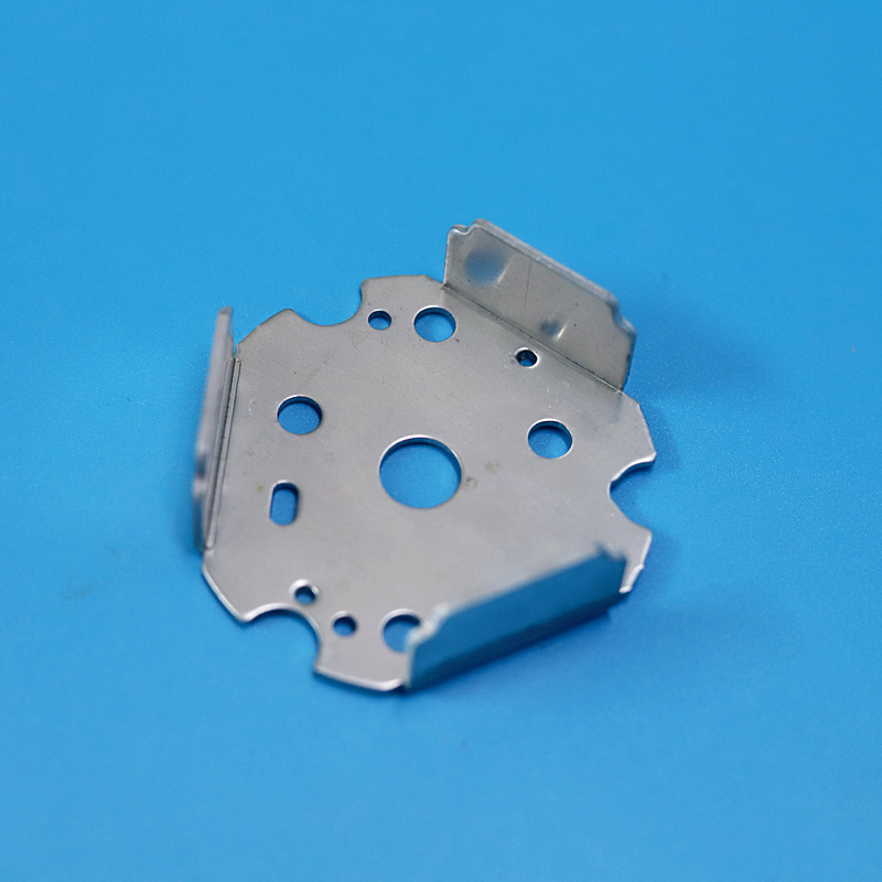
Sheet Metal Fabrication Principles and Industrial Uses
Custom sheet metal fabrication from Xuxiangtai. We manufacture reliable sheet metal components with cutting, forming and joining processes for global industrial buyers.
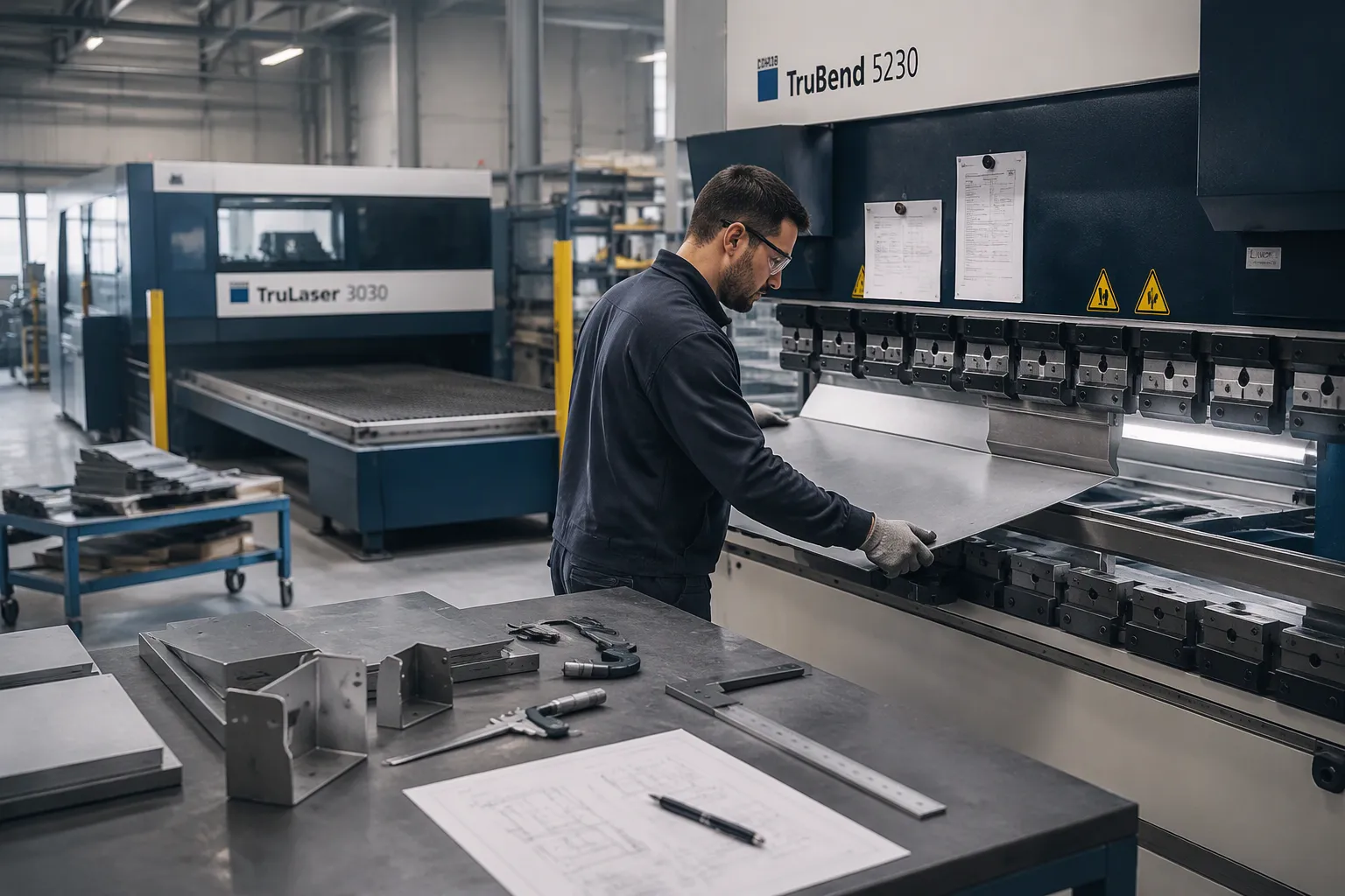
Sheet metal fabrication cuts, forms, joins, and finishes flat metal sheets into functional parts and structures. This core manufacturing method serves nearly every industrial sector. The process applies a defined set of operations to metals of varying thickness and composition. To write a professional and informative article about sheet metal fabrication and its industrial applications, one should explain the basic principles clearly, covering how cutting, forming, joining, and finishing operations transform flat metal sheets into functional parts and structures across nearly every industrial sector.
Key Takeaways
- Sheet metal fabrication uses cutting, forming, joining, and finishing to turn flat metal into useful parts.
- Choose the right metal and follow design rules to avoid cracks, warping, and extra costs.
- Industries like automotive and construction rely on sheet metal for strong, precise, and flexible production.
Sheet Metal Fabrication Principles: How It Works
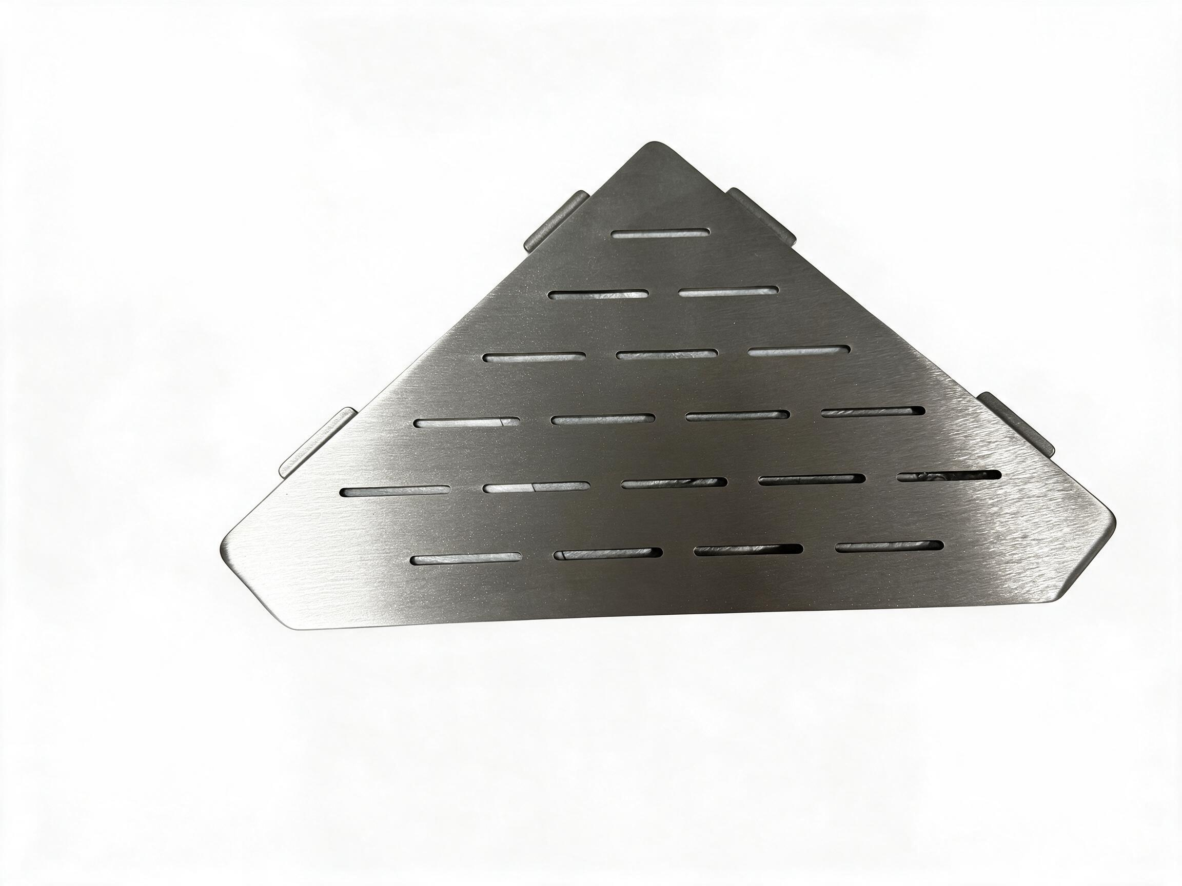
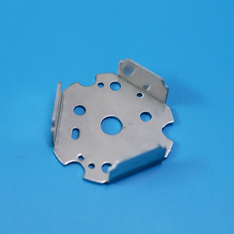
Sheet metal fabrication turns a flat sheet into a finished part through a sequence of controlled operations. Each operation changes the geometry, the surface, or the structure of the workpiece. The order of these operations matters. A part usually moves from cutting to forming, then to joining, and finally to finishing. To write a professional and informative article about sheet metal fabrication and its industrial applications, one must first explain the basic principles behind each operation. This section breaks the workflow into four core stages.
Cutting Processes
Cutting separates a large sheet into blanks with the required outline. The blank becomes the starting point for every later operation. Cutting accuracy directly affects the final dimensions of the part. A small error at this stage propagates through bending, welding, and assembly.
Laser cutting uses a focused beam to melt or vaporize metal along a programmed path. The method produces narrow kerfs and tight tolerances. Complex contours, small holes, and intricate nested layouts are all possible. Laser cutting suits both thin gauges and medium-thickness plates. The heat-affected zone stays small, so the edge quality remains high.
Plasma cutting relies on a high-velocity ionized gas jet. The process cuts thicker plate at higher speed than laser cutting. Edge squareness is good, though the kerf is wider. Plasma cutting fits structural work and heavy plate breakdown.
Waterjet cutting uses a high-pressure stream of water mixed with abrasive particles. The process is a cold cut. No heat-affected zone forms, so material properties stay unchanged. Waterjet cutting handles thick sections and heat-sensitive alloys well.
Shearing uses a straight blade to slice sheet along a line. The operation is fast and economical for straight cuts. Sheet shearing works best for rectangular blanks and trim cuts.
The choice of cutting method depends on material type, thickness, tolerance, and volume. A shop may combine several methods in one production plan. Laser cutting handles the intricate profiles, and shearing handles the simple rectangular blanks.
Bending and Forming
Bending and forming reshape a flat blank into a three-dimensional structure. The metal deforms plastically beyond its yield point. The material keeps the new shape after the load is removed.
Press brake bending is the most common forming operation. A punch presses the sheet into a V-shaped die. The angle of the bend depends on the punch travel and the die opening. Air bending, bottoming, and coining are three variants of this operation. Air bending offers the most flexibility. Coining produces the most accurate angle.
Bend radius is a critical parameter. A radius that is too tight causes cracking on the outer surface. The minimum bend radius depends on material ductility and thickness. A general rule sets the minimum radius near the sheet thickness for mild steel. Aluminum and high-strength steels need larger radii.
Springback is another key consideration. Metal tends to spring back slightly after the punch releases. The amount of springback grows with material strength. Operators compensate by overbending the part. Modern controllers calculate the compensation automatically.
Rolling and rounding form the sheet into cylinders or arcs. A set of rolls passes the sheet through successive bends. The process produces tanks, ducts, and curved panels. Rolling suits large-radius curves that a press brake cannot handle.
Stretch forming and deep drawing pull the sheet over a die. The material stretches into a concave or hollow shape. These operations produce enclosures, housings, and complex panels. The material must have enough ductility to stretch without tearing.
Pre-installation of hardware often happens during forming. Press nuts, standoffs, and rivet studs go into the sheet before the final assembly. This step simplifies later joining and reduces handling.
Welding and Assembly
Welding and assembly join separate components into a single structure. The joint must carry load and maintain dimensional accuracy. The joining method depends on material, thickness, and appearance requirements.
Spot welding passes current through overlapping sheets. Resistance at the interface generates heat and forms a weld nugget. Spot welding is fast and well suited to automated lines. Automotive body panels rely on this method heavily.
Arc welding, including MIG and TIG, creates a continuous seam. MIG welding feeds a consumable wire electrode. The process is fast and works well on thicker sections. TIG welding uses a non-consumable tungsten electrode. The operator controls the filler separately. TIG welding produces clean, precise seams on stainless steel and aluminum.
Laser welding offers high speed and a narrow heat-affected zone. The focused beam produces deep, narrow welds with low distortion. Laser welding suits precision components and thin-gauge assemblies.
Riveting provides a mechanical joint without heat. Rivets fix parts together through pre-drilled holes. The method avoids thermal distortion and works on dissimilar metals. Blind rivets allow joining from one side only. Self-clinching fasteners press into the sheet and create strong threaded connections.
Weld distortion is a common challenge. Localized heating causes the metal to expand and contract. The part may warp or lose flatness. Fabricators manage distortion through weld sequence, fixturing, and heat input control. A balanced weld pattern spreads the heat evenly across the assembly.
Assembly also includes fit-up and alignment. Fixtures hold the parts in position during joining. Accurate fit-up ensures the final product meets its tolerances. Inspection follows assembly to verify dimensions and joint quality.
Punching and Stamping
Punching and stamping use dies and presses to cut and shape sheet metal at high speed. These operations dominate high-volume production. A single stroke can produce a hole, a notch, or a complete blank.
Punching drives a punch through the sheet into a die. The operation creates holes, slots, and cutouts. The clearance between punch and die controls edge quality. Proper clearance produces a clean shear zone and minimal burr.
CNC punching combines many tools in one machine. A turret holds punches and dies of various sizes. The machine positions the sheet and fires the required tool. CNC punching handles both cutting and forming in one setup. Louvers, tabs, and embosses are all possible.
Stamping covers a family of die-based operations. Blanking cuts the outer profile of the part. Piercing cuts internal holes. Bending, drawing, and embossing form the shape within the die. A progressive die performs several operations in sequence. The strip advances one station at a time. Each stroke adds a feature. The final station ejects a finished part.
Stamping offers excellent repeatability and low unit cost at volume. Tooling cost is high, so the method fits long production runs. Die maintenance and setup time are the main considerations. A well-maintained die produces millions of consistent parts.
The four stages work as an integrated system. Cutting creates the blank, forming adds geometry, joining builds the structure, and punching or stamping delivers high-volume precision. To write a professional and informative article about sheet metal fabrication and its industrial applications, one should explain the basic principles of how these operations connect. Each stage builds on the accuracy of the one before it. A well-planned process sequence keeps tolerance stack-up under control and keeps production efficient.
Materials and Design Considerations
Material choice and design decisions shape every downstream operation in sheet metal fabrication. A part that suits its material will cut cleanly, bend without cracking, and hold its tolerances through welding and finishing. A poor match between material, geometry, and thickness creates defects that no amount of process skill can fully correct. This section examines the metals commonly used in fabrication, the criteria that guide material selection, the design rules that keep parts manufacturable, and the role of sheet thickness in cost and quality.
Common Metals Used
Fabricators work with a defined family of metals. Each metal brings a distinct combination of strength, formability, corrosion resistance, and cost. The table below summarizes the metals most often specified for industrial sheet metal work.
| Metal | Typical Strengths | Formability | Corrosion Resistance | Common Uses |
|---|---|---|---|---|
| Cold-rolled steel | Good strength, excellent surface finish | High | Low without coating | Enclosures, brackets, chassis |
| Hot-rolled steel | Higher strength, thicker gauges | Moderate | Low without coating | Structural frames, heavy brackets |
| Stainless steel | High strength, excellent corrosion resistance | Moderate | Excellent | Food equipment, medical parts, architectural panels |
| Aluminum | Light weight, good strength-to-weight ratio | High | Good (natural oxide layer) | Aerospace parts, electronics housings, signage |
| Copper and brass | High conductivity, attractive finish | High | Good | Electrical components, decorative parts |
| Galvanized steel | Good strength with zinc protection | Moderate | Good | HVAC ductwork, outdoor enclosures |
Cold-rolled steel offers a smooth surface and tight thickness tolerance. The material bends predictably and takes powder coating well. Hot-rolled steel costs less per pound at heavier gauges. Its surface carries mill scale, so it usually needs cleaning before finishing.
Stainless steel resists rust through a chromium oxide layer. The alloy work-hardens quickly during forming. Fabricators adjust bend radii and tooling to account for this behavior. Aluminum weighs roughly one-third as much as steel. The metal forms easily and resists corrosion in most environments. Its lower stiffness demands careful fixture design during machining and welding.
Copper and brass conduct electricity and heat exceptionally well. These metals suit bus bars, terminals, and decorative trim. Galvanized steel carries a zinc coating that sacrifices itself to protect the base metal. The coating demands care during welding because zinc fumes form at the arc.
Material Selection Criteria
Material selection balances functional requirements against cost and manufacturability. Engineers evaluate several criteria in parallel. No single criterion decides the choice on its own.
Mechanical strength tops the list for load-bearing parts. The designer compares the yield strength of candidate metals against the expected service loads. A safety factor covers uncertainty in loading and material properties. Weight-sensitive applications favor aluminum or thin-gauge high-strength steel. A part that must survive impact may need a thicker gauge or a tougher alloy.
Corrosion resistance follows closely. Outdoor parts, food processing equipment, and marine components demand stainless steel, aluminum, or a protective coating. Indoor parts in dry environments can use plain steel with paint. The service environment decides how much corrosion protection the part needs.
Formability governs whether the metal survives the bending and drawing operations. Ductile metals bend to tight radii without cracking. High-strength steels and some aluminum alloys limit the minimum bend radius. The designer checks the material’s elongation rating before specifying tight geometry.
Cost includes more than the raw metal price. Machinability, weldability, and finishing requirements all add to the total. Aluminum cuts fast but costs more per pound than steel. Stainless steel demands slower cutting speeds and more expensive welding gas. A life-cycle view often justifies a higher material cost for a longer service life.
Availability and lead time matter in production planning. Common grades ship from stock. Exotic alloys may carry long lead times. A proven, readily available grade usually beats a marginal performance gain from a rare alloy.
Design Guidelines
Good design keeps a part manufacturable at reasonable cost. Design rules translate fabrication physics into drawing practice. A designer who follows these rules avoids rework and scrap.
Keep the bend radius at or above the material’s minimum. A tight radius concentrates strain on the outer surface and invites cracking.
Hole placement deserves early attention. A hole too close to a bend distorts during forming. The standard rule sets the minimum distance from the hole edge to the bend line at two to three times the sheet thickness plus the bend radius. Holes near a bend also need relief slots to prevent tearing.
Bend relief protects the corners of a formed part. A small notch at the end of a bend line prevents tearing at the corner. The relief width typically matches the sheet thickness. Designers add relief whenever a bend terminates inside the part outline.
Uniform bend radii simplify tooling. A part with one or two bend radii uses fewer press brake setups. Each additional radius adds setup time and cost. Standardizing radii across a product family compounds the savings.
Tolerances should reflect real process capability. Laser cutting holds tight tolerances easily. Bending accumulates tolerance across multiple bends. A stack of five bends can drift noticeably from nominal. Designers specify realistic tolerances and avoid over-constraining dimensions that do not affect function.
Fastener and joint locations need clearance for tools. Welding guns, rivet setters, and nut drivers all require access. A joint buried in a corner forces awkward tooling or manual work. Designers mark tool access zones on the drawing.
Thickness Considerations
Sheet thickness drives nearly every cost and quality factor in fabrication. Thicker metal carries more load and resists denting. It also costs more, cuts slower, and demands more force to bend.
Cutting speed falls as thickness rises. A laser that slices thin gauge at high speed slows dramatically on thick plate. Plasma and waterjet take over at the heavy end of the range. The cut edge quality also changes with thickness. Thick sections show more taper and a rougher edge.
Bending force scales with thickness squared. Doubling the thickness quadruples the tonnage a press brake must deliver. The bend radius must also grow with thickness to avoid cracking. A rule of thumb sets the minimum inside radius at one times the thickness for mild steel. Aluminum and high-strength alloys need larger multipliers.
Thickness tolerance affects assembly fit. Mill standards allow a thickness range for each gauge. A stack of parts at the thick end of the range may not fit a fixture designed for nominal thickness. Designers account for this variation in critical assemblies.
Weight and cost follow thickness directly. A gauge reduction of one step can cut material cost by a meaningful margin. The designer must confirm that the thinner gauge still meets strength and stiffness requirements. Stiffness falls with the cube of thickness, so a small reduction weakens a panel far more than its weight savings suggest.
Gauge numbering adds a layer of care. The gauge system runs backward: a higher gauge number means thinner metal. Different metals use different gauge tables. A 16-gauge steel sheet is not the same thickness as 16-gauge aluminum. Drawings should state thickness in decimal units to remove ambiguity.
Material and design decisions connect directly to the fabrication sequence described earlier. The metal chosen determines the cutting method, the bend radius, and the welding process. The design rules determine whether those operations run smoothly. Thickness ties the whole picture together through its effect on force, speed, tolerance, and cost. A fabrication plan that respects these relationships produces parts that meet specification on the first pass.
Industrial Applications and Trade-Offs
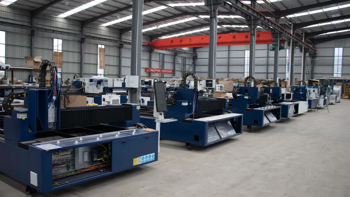
Sheet metal fabrication serves many sectors because it balances strength, precision, and production flexibility. Each industry applies the same core operations to different ends.
Automotive and Aerospace
Automotive production relies on stamping and spot welding for body panels, chassis parts, and brackets. High-volume lines demand fast cycle times and consistent repeatability. Aerospace work shifts toward aluminum and titanium components. Laser cutting and precision forming produce lightweight structures with tight tolerances. Both sectors prioritize weight reduction and structural integrity.
Construction and Architecture
Construction uses sheet metal for roofing, cladding, ductwork, and structural connectors. Galvanized steel and aluminum resist weather exposure. Architectural panels demand excellent surface finish and precise bend angles. Metal structures and equipment brackets anchor mechanical systems in buildings. Fabricators balance durability against material cost on every project.
Electronics and Machinery
Electronics housings require thin-gauge aluminum or cold-rolled steel. Machine enclosures protect internal components and manage heat. CNC punching creates ventilation slots, mounting holes, and cable cutouts in one setup. Equipment brackets carry motors, sensors, and control units. Dimensional accuracy and hole positioning directly affect assembly fit.
Advantages and Limitations
| Advantages | Limitations |
|---|---|
| High strength-to-weight ratio | Tooling cost for stamping |
| Fast, repeatable production | Thickness limits on forming |
| Flexible design changes | Weld distortion risk |
| Wide material choice | Tolerance stack-up across bends |
Custom sheet metal parts manufacturing and OEM services build to customer drawings, samples, and technical specifications. International customers can submit drawings and technical documents for a fabrication quote.
Sheet metal fabrication combines cutting, forming, and assembly operations. These steps turn flat metal into functional parts. Each stage builds on the accuracy of the one before it.
Material choice, design guidelines, and thickness directly affect part quality and cost. A well-matched metal bends cleanly and holds its tolerances. Sound design rules prevent defects and rework.
The method serves diverse industries well. It balances strength, precision, and production flexibility. Automotive, aerospace, construction, and electronics all rely on this balance.
FAQ
How Do I Choose the Right Metal for My Part?
Match the metal to the service environment and load. Stainless steel suits wet or corrosive settings. Aluminum saves weight. Plain steel works indoors with a protective coating.
Does Sheet Thickness Really Affect Cost That Much?
Yes. Thicker sheets cut slower and need more bending force. Material weight rises too. A one-gauge reduction often lowers total part cost noticeably.
Which Operation Comes First in the Fabrication Sequence?
Cutting comes first. The blank defines every later dimension. Forming follows cutting, then joining, then finishing. This order keeps tolerance stack-up under control.
See Also
Avoid Making Incorrect Decisions When Selecting Aluminum Casting Methods
Related products
-
 Contact Us
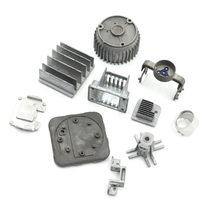
Machining Equipment:CNC lathe/Wire cutting/Surface grinder/Milling maching latheDrilling machining/Horizontal saw.
-
 Contact Us
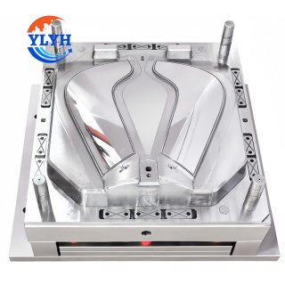
Place of Origin:Shenzhen,China
Model Number:OEM/ODM
Product:Plastic Injection Mould
Application:Automotive Equipment
Mould material:H13/P20/NAK80/S136/2738/2316/S7/1.2344
Mould Life:250000-300000shots
Surface treatment:Polishing
Certification:ISO9001 ISO13485 IATF16949 -
 Contact Us
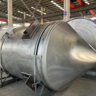
The vacuum feeding tank is the core component of the EB furnace melting system. responsible for feeding raw materials (such as titanium sponge, titanium residue or titanium alloy waste) into the melti
-
 Contact Us
● HIGH EFFICIENCY / SMALL FOOTPRINT / QUICK CHANGEOVER / INFORMATIZATION
● LEADING TECHNOLOGY / SIMPLE OPERATION
Reviews
There are no reviews yet.