

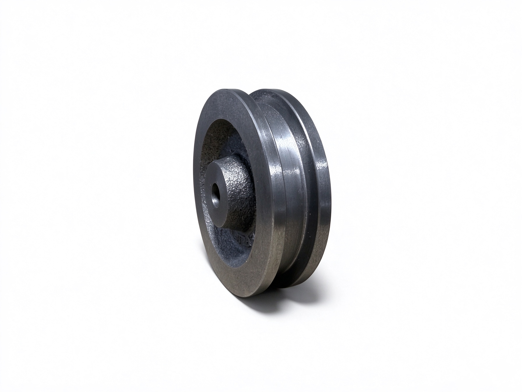

A Guide to Contaminant Control in Precision Cast Metal Parts
Master contaminant control for precision cast metal parts. Filtration, finishing and inspection solutions from Xuxiangtai Machinery.
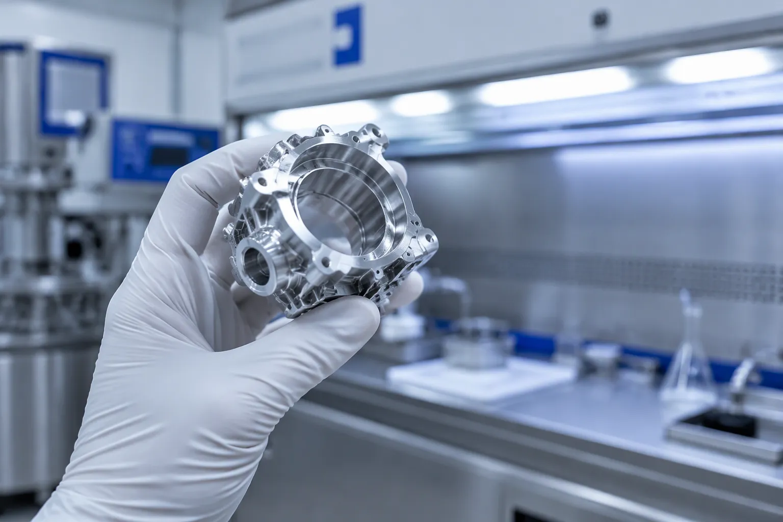
Internal cavity cleanliness determines whether a precision cast part meets performance, reliability, and acceptance requirements. Trapped contaminants cause fluid turbulence, sediment buildup, corrosion initiation, and dimensional nonconformance. Four contaminant families dominate casting and machining operations: residual ceramic shell and sand, machining fluids and coolants, metallic debris and chips, and handling-introduced foreign matter. Effective control is a process discipline. Engineers design it into part geometry and casting parameters, execute it through matched cleaning methods, verify it by inspection, and preserve it through handling controls. Write a professional article about internal cavity cleanliness in precision cast metal parts for US mechanical engineers to document this discipline.
Key Takeaways
- Identify the main contaminant sources in your casting and machining processes to control them early.
- Match cleaning methods to the specific contaminant and part geometry for effective removal.
- Verify cleanliness with inspection and control handling to prevent recontamination.
Write a Professional Article About Internal Cavity Cleanliness: Contaminant Sources and Process Drivers
Residual Sand and Ceramic Shell Materials
Investment casting leaves ceramic shell fragments and loose sand inside cavities. Shell removal, knockout, and cut-off operations drive these residues into recessed areas. Incomplete dewaxing and weak shell strength increase the risk. Blasting media can also embed in soft surfaces.
Machining Fluids, Chips, and Foreign Matter
Machining introduces coolant, cutting fluid, and metallic chips. Blind holes and internal passages trap these materials. Handling adds dust, glove fibers, and packaging debris. Each source demands a different control response.
How Contaminants Degrade Part Performance
Trapped particles disturb fluid flow and create turbulence. Sediment accumulates in low-velocity zones. Residual chlorides and moisture initiate corrosion. Chips interfere with dimensional checks and assembly fit. These effects shorten service life and trigger rejection.
Part Geometry and Cavity Accessibility
Cavity shape governs cleaning difficulty. Long, narrow passages resist flow. Sharp internal corners hold debris. Designers who open access and round transitions make cleanliness achievable. Engineers reviewing geometry early prevent cleaning problems later.
Casting Parameters That Drive Contamination
Several process variables influence internal cleanliness:
| Parameter | Effect on Contamination |
|---|---|
| Shell thickness and slurry quality | Weak shells shed fragments |
| Dewaxing cycle | Incomplete removal leaves carbon residue |
| Pouring temperature | Low temperature traps inclusions |
| Knockout method | Aggressive removal drives sand inward |
Engineers who write a professional article about internal cavity cleanliness in precision cast metal parts for US mechanical engineers must treat these parameters as cleanliness controls, not just yield controls. A second look at the same variables shows how process discipline starts at the pattern stage.
Matching Cleaning Methods to Contaminant and Geometry
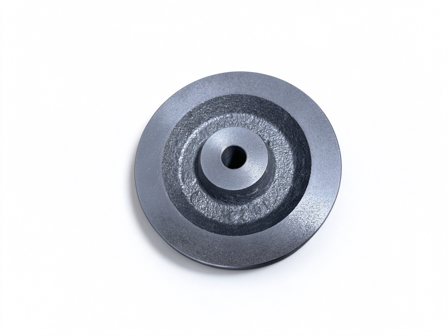
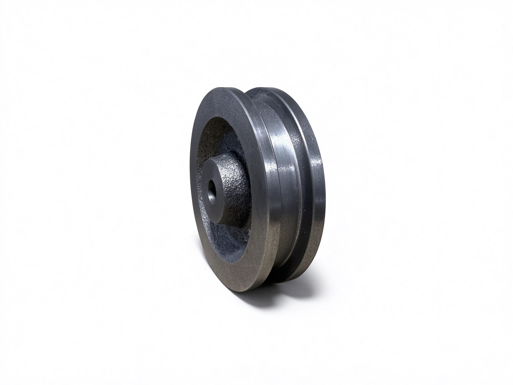
Cleaning method selection is a two-variable problem. The contaminant family sets the removal mechanism. The cavity geometry sets the delivery method and the reachable energy at the cavity surface. A method that works well on shell residue in an open bowl may fail completely on coolant trapped in a 3 mm cross-drilled passage. Engineers who write a professional article about internal cavity cleanliness in precision cast metal parts for US mechanical engineers must treat method selection as an engineering match, not a shop-floor default.
Mechanical and Thermal Cleaning
Mechanical methods remove contamination through physical force. Shot blasting, grit blasting, and tumbling break loose shell and sand from external and accessible internal surfaces. Abrasive flow machining pushes a viscous abrasive medium through internal passages. The medium shears residue from the wall and carries it out of the cavity. Abrasive flow suits cross-drilled holes, hydraulic manifolds, and other passages with a defined inlet and outlet. The method reaches zones that no spray nozzle can touch. Media selection matters. A coarse medium removes heavy shell fast and leaves a rougher wall. A fine medium polishes the surface and improves the final finish.
Thermal methods rely on temperature to eliminate contamination. A controlled burn-off cycle vaporizes wax residue, carbon deposits, and organic machining oils. Heat treatment under vacuum or a protective atmosphere can drive off absorbed moisture and volatilize hydrocarbon films. Thermal cleaning offers a real advantage: it reaches every internal surface that the furnace atmosphere reaches. Complex internal cores and blind cavities receive the same treatment as exposed faces. The method has limits. It does not remove inorganic sand or ceramic fragments. It does not remove metallic chips. Thermal cycles also consume energy and add process time, so engineers reserve them for organic contamination and for parts that need a clean, dry internal surface before final assembly.
Mechanical and thermal methods often work as a pair. Blasting or abrasive flow removes the bulk inorganic residue. A thermal cycle then eliminates the organic film that remains. This sequence prevents the smearing problem. A blasting operation that runs on an oil-coated surface can push oil and fines deeper into the wall. Removing the oil first, or removing the bulk solids first and then burning off the oil, keeps each step effective.
Chemical, Aqueous, and Ultrasonic Cleaning
Chemical cleaning dissolves or chemically alters the contaminant. Pickling with an acid solution removes oxide scale, heat tint, and embedded iron from stainless surfaces. Passivation follows pickling and restores the chromium oxide layer that gives stainless steel its corrosion resistance. These steps matter for 316 stainless parts that serve chloride or acidic media. A cavity with residual free iron or a disrupted passive film becomes a corrosion initiation site. Chemical cleaning reaches internal surfaces by immersion, so the bath contacts every wetted area. The method demands process control. Bath concentration, temperature, and dwell time all affect results. Rinsing must be thorough, because residual acid or salt becomes a new contaminant.
Aqueous cleaning uses water-based detergents, often with heat and agitation, to lift oils, coolants, and loose particles. Pressure washing delivers the chemistry with force. Spray-in-air and spray-in-liquid systems direct a jet into internal passages. The jet reaches line-of-sight surfaces well. It loses energy around bends and in dead-end cavities. Aqueous systems are compatible with most metals and carry low operator and environmental risk. Waste treatment is straightforward. The method fits high-volume production and parts with open, accessible geometry.
Ultrasonic cleaning adds a third mechanism: cavitation. Transducers drive high-frequency sound waves through a liquid bath. The waves form and collapse microscopic bubbles. The collapse generates localized energy at the part surface and lifts contamination from blind holes, threads, and fine internal features. Ultrasonic cleaning excels where fluid flow cannot reach. A blind tapped hole, a narrow slot, or a porous cast surface all respond well to cavitation. Frequency selection tunes the process. Lower frequencies produce larger bubbles and stronger energy for heavy soil. Higher frequencies produce smaller bubbles and gentler action for fine features and delicate surfaces. Ultrasonic cleaning works best as a stage in a multi-step line: a detergent stage for organics, a rinse stage, and often a final deionized water rinse and dry.
Selection Criteria by Contaminant Type
The contaminant family narrows the method list. The table below summarizes the primary match for each family.
| Contaminant | Primary Methods | Notes |
|---|---|---|
| Ceramic shell and sand | Blasting, abrasive flow, high-pressure aqueous | Inorganic residue resists chemical dissolution |
| Machining fluids and coolants | Aqueous detergent, ultrasonic, thermal burn-off | Organics need surfactant or thermal removal |
| Metallic chips and fines | Abrasive flow, flushing, ultrasonic | Chips lodge in low-velocity zones |
| Handling foreign matter | Aqueous rinse, ultrasonic, clean handling | Prevention is cheaper than removal |
Ceramic shell and sand resist chemical attack. Mechanical energy removes them. Blasting handles external and open surfaces. Abrasive flow handles internal passages. High-pressure aqueous jets handle accessible cavities with a clear line of sight. Machining fluids and coolants respond to surfactants and heat. An aqueous detergent stage lifts the oil film. An ultrasonic stage dislodges oil from blind features. A thermal cycle volatilizes the residue when the part geometry blocks fluid access. Metallic chips need a transport mechanism. Abrasive flow carries chips out of a passage. A directed flush does the same job in a simpler geometry. Ultrasonic cavitation loosens fines that cling to the wall. Handling foreign matter, such as dust and glove fibers, yields to a rinse and a controlled dry. The better answer is to stop the contamination at the source with gloves, covers, and clean packaging.
Selection Criteria by Cavity Geometry
Geometry decides whether a method can deliver its energy to the contamination. Open cavities accept almost any method. The engineer chooses on cost, cycle time, and surface finish requirements. Long, narrow passages change the calculation. A spray jet loses pressure along the passage length. A detergent bath may not exchange fluid inside a dead-end hole. Abrasive flow works well here, because the medium fills the passage and shears the wall along its full length. Ultrasonic cleaning also performs well, because cavitation reaches into narrow features that fluid flow cannot flush.
Blind holes and internal corners present the hardest case. Fluid stagnates at the bottom of a blind hole. Debris settles in the corner radius. Ultrasonic cleaning is the strongest single method for these features. A vacuum-assisted rinse adds a second option. The vacuum pulls air from the cavity, and the rinse liquid fills the void when the pressure returns. This cycle exchanges the fluid in a dead-end feature that a simple immersion cannot reach.
Cavity size sets the energy requirement. A large internal volume needs a high flow rate to exchange the bath. A small cavity needs fine filtration, because a particle that passes a large filter can lodge in a small passage. Engineers should set the filter rating below the smallest critical clearance in the part. A 50-micron filter does not protect a 200-micron passage.
Surface finish requirements interact with method choice. Abrasive flow improves the wall finish and can raise the corrosion resistance of a stainless passage. Blasting roughens the surface and can embed media. A part that needs a sanitary or high-purity internal finish should avoid aggressive blasting inside the cavity. Electropolishing offers a final option for 316 stainless parts. The process removes a thin uniform layer from the internal surface, smooths microdefects, and leaves a passive, easy-to-clean wall. Electropolishing suits semiconductor, pharmaceutical, and high-purity fluid service. It complements the mechanical and chemical steps rather than replacing them.
A practical selection sequence follows four steps. First, identify the dominant contaminant family. Second, map the cavity geometry and mark the zones that each candidate method can reach. Third, confirm material compatibility, especially for stainless parts that need passivation or electropolishing. Fourth, validate the choice with an extraction test on a first-article part. This sequence keeps method selection tied to evidence. It also gives the process engineer a documented rationale for each cleaning step.
Inspection, Validation, and Preventing Recontamination
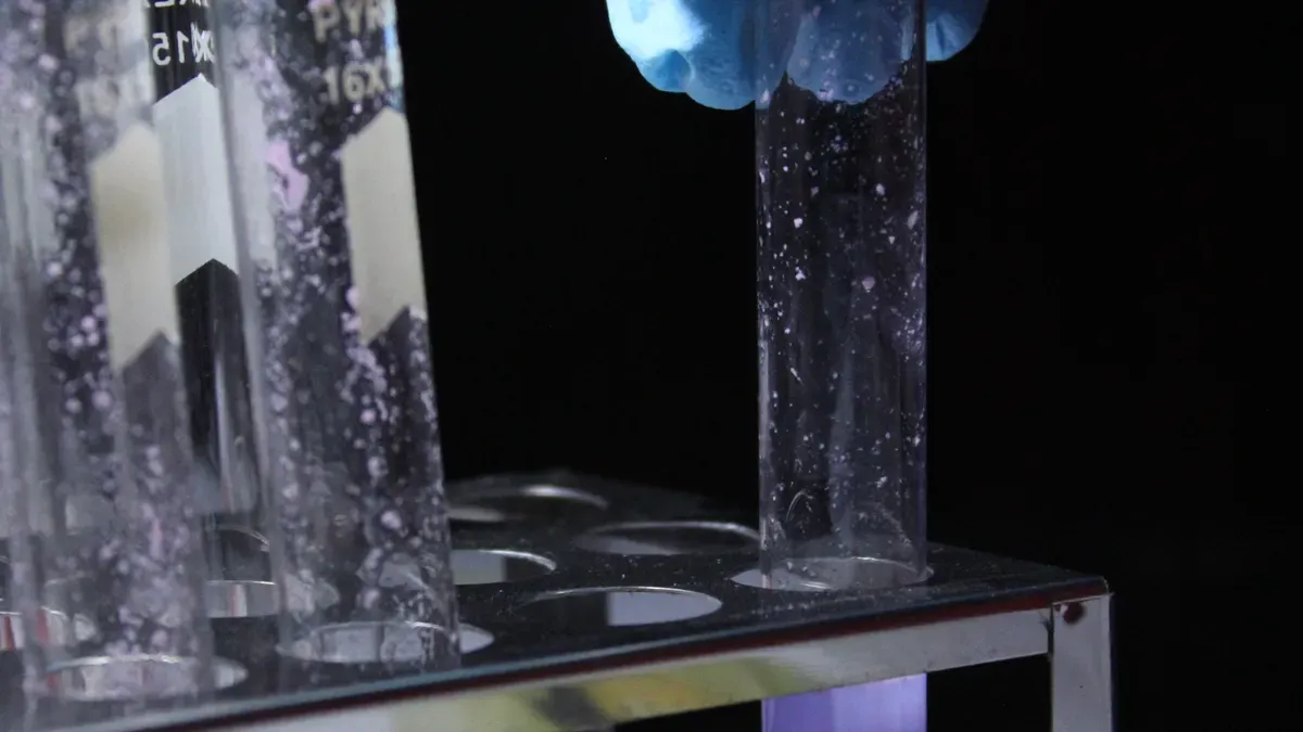
Cleaning removes contamination. Inspection proves the removal worked. Handling controls keep the part clean after inspection. These three activities form a closed loop. A gap in any one of them breaks the chain. A part that passes a borescope check can still fail at the customer’s incoming inspection if a technician handles it with bare hands. Engineers who write a professional article about internal cavity cleanliness in precision cast metal parts for US mechanical engineers must treat inspection and handling as equal partners to cleaning, not as afterthoughts.
Visual, Borescope, and Dimensional Checks
Visual inspection is the first line of verification. A trained inspector examines accessible internal surfaces under adequate lighting. The inspector looks for loose sand, shell fragments, chips, oil films, and discoloration that signals corrosion or heat damage. Visual inspection is fast and inexpensive. It also has a hard limit: the human eye sees only what the line of sight reaches. A straight passage with a 20 mm diameter accepts direct viewing. A curved 4 mm passage does not.
Borescope inspection extends the line of sight into cavities that direct viewing cannot reach. A rigid borescope suits straight passages and provides a stable image. A flexible fiberscope or video borescope navigates bends, elbows, and complex internal cores. Modern video borescopes record still images and video, which gives the quality engineer a permanent record for the inspection report. Magnification reveals fine residue that a naked eye misses. The inspector can measure defect size against a reference scale in the field of view.
Borescope technique matters as much as the instrument. The inspector must sweep the full cavity surface, not just the entry and exit. A common error is to check the first 10 mm of a passage and declare it clean. Contamination often collects at the far end, in a low-velocity zone, or behind a bend. A written inspection route that specifies each zone to be viewed keeps the check repeatable across shifts and inspectors.
Dimensional checks catch a different class of problem. Trapped chips and residual shell can distort a measured feature. A bore gauge reading that drifts between parts may signal debris in the bore, not a machining error. Coordinate measuring machine (CMM) probes can contact contamination and report a false dimension. Inspectors should clean and verify the measurement surface before a critical dimensional check. A dimensional nonconformance that appears only on parts from one mold or one machining lot points to a contamination source, not a tool wear issue.
The three checks work as a sequence. Visual inspection screens every part. Borescope inspection samples critical cavities or covers 100 percent of parts for high-purity service. Dimensional checks confirm that contamination has not altered fit or function. The inspection plan should state which check applies to which cavity, at what frequency, and with what acceptance criteria.
Extraction-Based Cleanliness Verification
Visual and borescope methods detect what the inspector can see. They cannot quantify a thin film of oil, a sub-micron particle, or a residue that clings to the wall in a transparent layer. Extraction-based verification fills this gap. The method flushes a controlled volume of clean fluid through the cavity, collects the fluid, and measures what it carries.
Three measurement approaches dominate production verification:
| Method | What It Measures | Typical Use |
|---|---|---|
| Gravimetric (filter residue) | Mass of particulate captured on a filter | General particulate cleanliness |
| Particle counting | Number and size distribution of particles | Hydraulic and high-purity systems |
| Non-volatile residue (NVR) | Mass of dissolved and suspended residue after evaporation | Oil films and chemical residue |
Gravimetric testing passes a known volume of filtered solvent or water through the cavity. A pre-weighed filter captures the particulate. The inspector dries and weighs the filter. The mass gain reports the particulate load in milligrams per part or per unit area. The method is simple, traceable, and easy to document. It suits general industrial parts and first-article qualification.
Particle counting pushes the flush fluid through an optical or electrical sensor. The sensor counts particles in size bands, such as greater than 5 microns, 15 microns, and 25 microns. The result is a size distribution, not a single mass. Hydraulic manifolds, fuel system components, and semiconductor fluid parts often specify cleanliness by particle count and maximum particle size. The specification ties directly to the smallest critical clearance in the system. A particle larger than the clearance can jam a valve or score a seal.
Non-volatile residue testing evaporates the collected flush fluid and weighs the residue. The method detects oil films, surfactant residue, and dissolved salts that a particulate filter passes through. NVR is the right check for parts that receive aqueous cleaning or chemical passivation. A part can pass a particulate test and still fail an NVR limit if rinse water leaves a mineral film.
Extraction parameters must be fixed and documented. Flow rate, flush volume, nozzle position, and fluid temperature all affect the result. A change in any parameter changes the measured value. The test method should specify each parameter and require revalidation after any process change. First-article inspection establishes the baseline. Periodic audits confirm that the process holds the baseline over time.
Fixturing, Drying, and Handling Controls
A clean part becomes a contaminated part the moment it leaves the cleaning line. Recontamination is the most common cause of a cleanliness failure at final inspection. The controls that prevent it are simple, cheap, and easy to skip. That combination makes them the weakest link in most shops.
Drying is the first control point. Residual moisture in a cavity promotes corrosion and provides a transport medium for particles. Water trapped in a blind hole can carry dissolved salts that later crystallize on the wall. Drying methods include forced hot air, vacuum drying, and solvent displacement. Hot air works for open cavities. Vacuum drying pulls moisture from blind holes and narrow passages. Solvent displacement uses a volatile solvent to carry water out of the cavity, and the solvent then evaporates. The choice depends on geometry and material. A 316 stainless part with a blind hole benefits from vacuum drying. A part with a complex internal core may need both a solvent flush and a vacuum cycle.
Fixturing protects the cleaned surface during drying, inspection, and transport. A fixture that contacts the internal cavity can transfer oil, dust, or metal particles. Clean fixtures with dedicated contact surfaces reduce this risk. Fixtures should be cleaned on the same schedule as the parts they hold. A fixture stored on an open bench collects dust. A covered or bagged fixture stays clean.
Handling controls address the human element. Bare hands deposit oils and salts. Gloves are mandatory for any part with a cleanliness specification. Glove material matters. Latex and nitrile gloves shed particles and can leave residue. Powder-free nitrile or cleanroom-grade gloves suit high-purity parts. Gloves must be changed at a defined frequency and never reused across a shift without cleaning.
Packaging closes the loop. A clean part placed in a dusty bag becomes contaminated. Packaging should match the cleanliness level of the part. Options range from simple polyethylene bags for general industrial parts to cleanroom-compatible packaging with desiccant and humidity indicators for high-purity service. Each part should carry a cleanliness label that records the inspection date, the method used, and the acceptance result. The label gives the customer traceability and signals that the part received controlled handling.
A cleanliness specification without a handling control is a specification the shop cannot hold. The part passes inspection in the morning and fails at the customer’s dock in the afternoon.
Integrating Control into the Manufacturing Process
Cleanliness is a process output, not an inspection activity. A shop that inspects cleanliness at the end of the line is measuring the result of every upstream decision. A shop that designs cleanliness into the process controls the result. The difference shows up in scrap rate, rework cost, and customer complaints.
Integration starts at the drawing review. The engineer examines cavity geometry for cleaning access. A blind hole with no vent, a sharp internal corner, or a passage narrower than the available cleaning nozzle all raise a flag. The engineer can propose a design change, such as a rounded transition or a vent hole, that makes cleaning achievable. A design change at the drawing stage costs almost nothing. The same change after casting and machining costs a rework cycle.
Integration continues at the casting stage. Shell quality, dewaxing cycle, pouring temperature, and knockout method all drive internal contamination. These parameters belong in the process control plan, not just the yield report. A shell that sheds fragments during knockout sends sand into every cavity. A dewaxing cycle that leaves carbon residue creates a film that later cleaning must remove. The casting engineer who treats these variables as cleanliness controls prevents contamination at the source.
Integration extends to machining. Coolant selection, chip evacuation, and in-process flushing all affect the internal cavity. A coolant that leaves a heavy oil film demands a stronger cleaning stage. A machining sequence that traps chips in a blind hole demands a directed flush before the part leaves the machine. In-process cleaning at the machine reduces the load on the final cleaning line and shortens the overall cycle.
The final piece is documentation. A cleanliness control plan should record the contaminant families present, the cleaning method for each, the inspection method and frequency, the acceptance criteria, and the handling controls. The plan gives the shop a repeatable process and gives the customer evidence that the process is under control. When a nonconformance appears, the plan shows which step failed and where to correct it.
Qingdao Xuxiangtai Machinery Manufacturing Co., Ltd. builds this integration into its service model. The company provides precision casting, CNC machining, and custom metal manufacturing services under one roof. Its investment casting process uses silica sol refractory slurry for high-quality ceramic shells, and its 316 stainless steel parts meet ASTM A351 CF8M, AISI 316, ASME B16.11, GB/T 14626, and HG/T 21634 standards. The company offers surface finish options that include pickling and passivation, mechanical polishing, and electropolishing, which support internal cavity cleanliness for chemical, marine, food, pharmaceutical, semiconductor, and energy applications. Its quality assurance includes 100 percent dimensional inspection, material reports, and non-destructive testing such as PT, RT, and pressure testing.
Customers with a cleanliness-critical application can submit drawings, samples, or technical specifications for a custom manufacturing inquiry. The engineering team reviews cavity geometry, contaminant risk, and inspection requirements at the quotation stage. This early review aligns cleaning and inspection steps with casting and machining parameters, so the delivered part meets its internal cavity cleanliness specification rather than merely passing a final visual check.
Best practice follows a fixed sequence. Engineers categorize the contaminant, match the cleaning method to contaminant and cavity geometry, verify with inspection, and control handling to prevent recontamination. Cleanliness is designed and maintained throughout the process, not inspected in at the end. Geometry, casting parameters, and fixturing decisions made early determine how achievable cleanliness will be. Partners with integrated casting, machining, and finishing capabilities, such as Qingdao Xuxiangtai Machinery Manufacturing Co., Ltd., which provides precision casting, CNC machining, and custom metal manufacturing services, can align cleaning and inspection steps with casting and machining parameters to hold internal cavity cleanliness to specification. Engineers who write a professional article about internal cavity cleanliness in precision cast metal parts for US mechanical engineers should treat this sequence as the standard.
FAQ
Which contaminant family causes the most internal cavity failures?
Residual ceramic shell and sand cause the most failures. These inorganic particles resist chemical cleaning and lodge in low-velocity zones. Mechanical methods such as abrasive flow remove them effectively.
How does a shop verify cleanliness in a blind hole?
Ultrasonic cleaning removes contamination from blind holes. Extraction-based testing then flushes the cavity and measures particulate or non-volatile residue. Vacuum-assisted rinsing exchanges fluid in dead-end features.
When should engineers specify electropolishing for internal cavities?
Engineers specify electropolishing for high-purity service in semiconductor, pharmaceutical, and sanitary applications. The process smooths microdefects and leaves a passive, easy-to-clean wall on 316 stainless parts.
See Also
Avoid Making Incorrect Aluminum Casting Process Choices Ever Again
Related products
-
 Contact Us
Deep groove bearings are a widely used bearing type known for their simple design and excellent performance.
-
 Contact Us
The company’s main products are high precision involute cylindrical gears,We specialize in manufacturing of gears products such as spur gear,helical gear, herringbone gear, external spline…
-
 Contact Us
Three-phase EI lamination is made by the silicon steel strip. The model of three-phase EI lamination is from three-phase(20) to three-phase(100), and the hole size is from Φ4.5 to Φ14. The gap sizes o
-
 Contact Us
We are ATLAS COPCO 3001500626 MPV KIT supplier and provide replacement parts for major air compressor manufacturers.
-
 Contact Us
Differential Transformer Displacement Sensors (LVDTs) can be widely used in various industries of the national economy, such as aerospace, machinery, construction, textiles, railways, coal, metallurgy
Reviews
There are no reviews yet.