

Quality Control in Forged and Machined Custom Metal Parts for Equipment Manufacturers
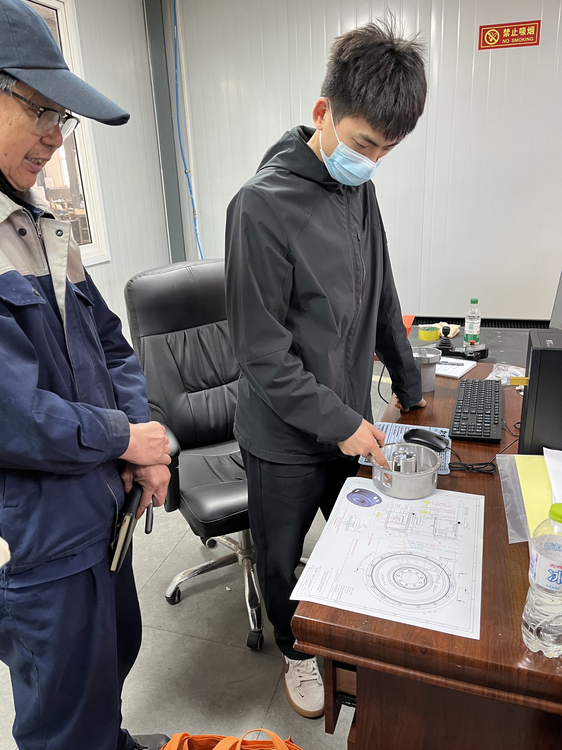
Forging & machining QC guide for custom metal parts, from material inspection to final testing by Xuxiangtai.
One undetected forging void or out-of-tolerance machined bore can halt an assembly line and erode end-user trust. Quality control for custom metal parts demands continuous discipline across two processes. Forging and machining each introduce distinct defect risks. This professional article about the integration of forging and CNC machining in custom metal part manufacturing shows how layered QC protects dimensional accuracy, structural integrity, and delivery schedules.
Key Takeaways
- Forging quality control starts with raw material checks and continues through in-process and final inspections to catch hidden defects.
- CNC machining quality control uses in-process checks, precise measurements, and surface finish tests to ensure repeatable parts.
- Integrated traceability links every part to its source and inspection records, giving manufacturers confidence and a competitive edge.
Quality Control in Forging: From Raw Material to Final Inspection
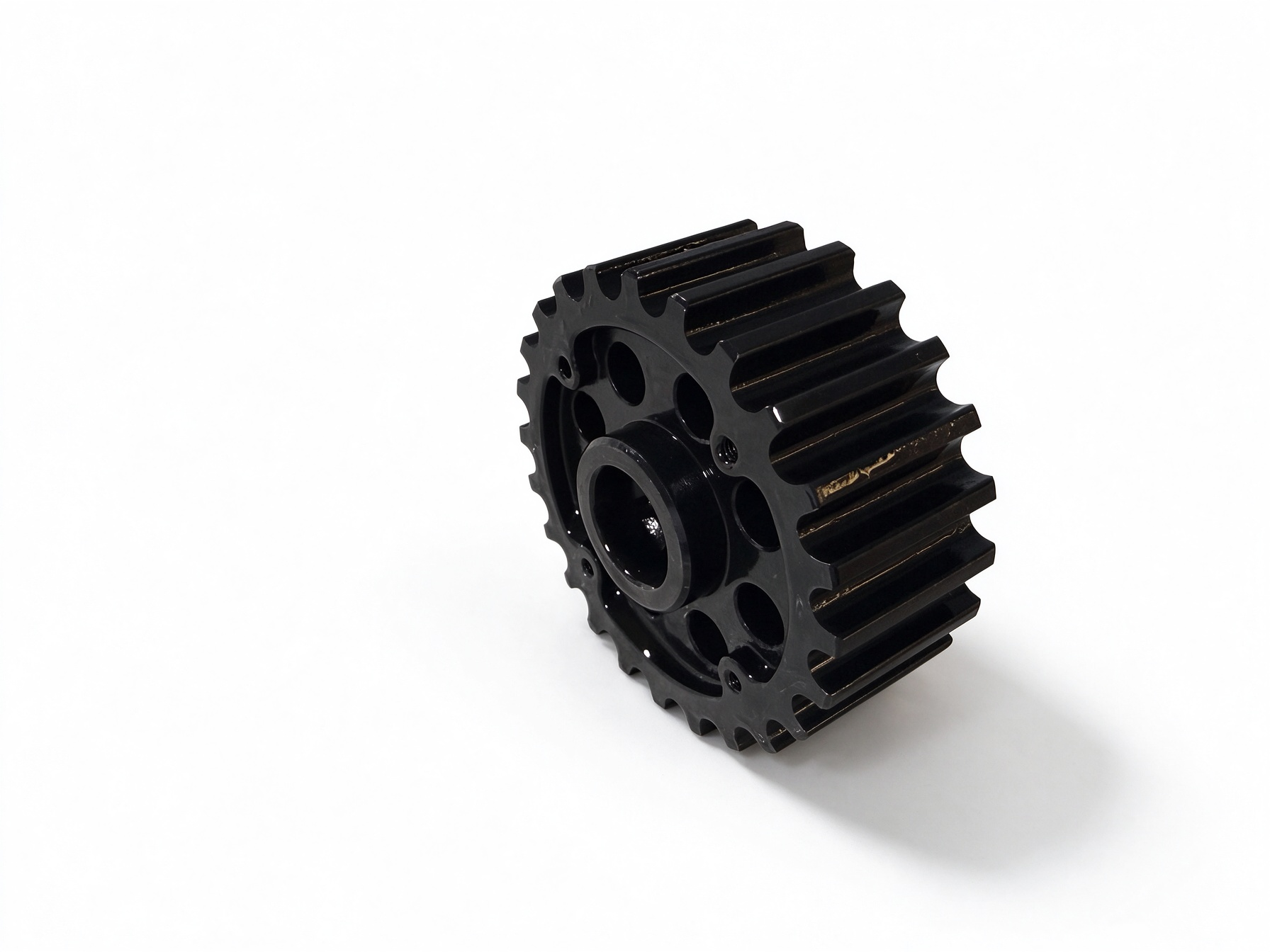
Forging quality control begins long before the hammer strikes the billet. A forging defect that escapes detection at any stage becomes a structural liability in the finished part. Equipment manufacturers depend on forged components for load-bearing duty. Oil pump gears, transmission shafts, and gear blanks must survive continuous impact and fatigue. Each production stage therefore carries its own inspection gate. The forging process moves through three distinct control phases: raw material verification, in-process inspection, and final testing.
Raw Material Verification and Certification
The quality of a forged part starts with the steel that enters the furnace. Material verification confirms the chemical composition and mechanical properties of every incoming heat. Suppliers must provide mill test certificates for each batch. These certificates document the steel grade, heat number, and ladle analysis. A quality team cross-checks the certificate against the purchase specification before releasing the material to production.
High-grade carburizing steels such as 18Xh3a demand strict chemistry control. Carbon, chromium, and nickel content directly influence hardenability and core toughness. A slight deviation in alloy balance can shift the case depth response during heat treatment. Spectrochemical analysis verifies the composition of each heat. Mechanical testing then confirms tensile strength, yield strength, and impact toughness. Only material that passes both checks moves forward.
Traceability links every forged part back to its source heat. The heat number follows the material through cutting, heating, forging, and machining. This chain allows a full investigation if a defect appears later. A documented material certificate and a verified heat number form the foundation of the entire quality record.
In-Process Forging Inspection
In-process inspection monitors the forging operation while the metal is still hot. Billet heating temperature ranks as the first critical parameter. Steel that overheats develops coarse grains and loses toughness. Steel that underheats resists die filling and creates laps or folds. Operators measure billet temperature before each strike. Pyrometers and thermocouples provide real-time readings against the approved process window.
Die condition receives attention at every setup and at defined intervals during the run. Worn dies produce parts with incorrect dimensions and poor surface quality. Inspectors check die alignment, wear depth, and cavity condition. A die with excessive wear goes to refurbishment before it affects the part.
The forging stroke itself demands monitoring. Press load, ram speed, and dwell time all shape the final grain structure. Continuous fiber flow lines follow the die contour and deliver the impact resistance that makes forged parts superior. Inspectors verify fiber flow direction on sectioned samples from the first production pieces. Any fold, lap, or unfilled corner signals a process adjustment.
Dimensional checks occur at the press during production. Operators measure thickness, diameter, and draft angles on hot or warm parts. These early measurements catch die drift before it produces a full batch of out-of-tolerance forgings. Statistical process control charts track the measurements over time. A trend toward the tolerance limit triggers a die correction.
Final Forging Inspection and Testing
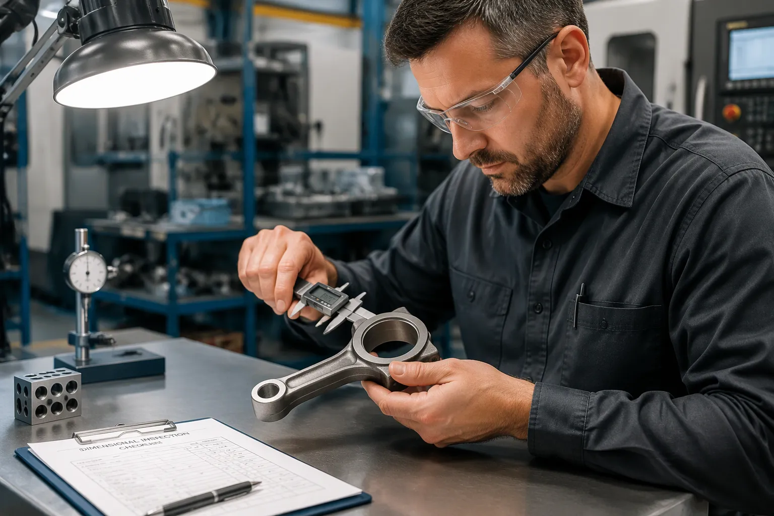
Final inspection confirms that the completed forging meets every drawing requirement. The inspection plan defines the sample size, the measurement method, and the acceptance criteria for each characteristic. Dimensional verification covers all critical features: overall dimensions, fillet radii, draft angles, and machining allowances. Coordinate measuring machines and dedicated gauges provide the required accuracy.
Internal integrity testing protects against hidden defects. Ultrasonic testing detects internal voids, inclusions, and shrinkage that visual inspection cannot reveal. The test sends high-frequency sound waves through the forging and reads the echo pattern. A void or inclusion reflects the signal and appears on the display. Critical parts receive 100% ultrasonic inspection. Magnetic particle inspection then reveals surface-breaking discontinuities such as cracks and laps.
Hardness testing verifies the heat treatment response. Surface hardness in the range of HRC 58–62 supports wear resistance at the tooth flank or bearing surface. Core hardness in the range of HRC 32–45 maintains toughness under impact load. A hardness traverse from surface to core confirms the case depth and the hardness gradient. Metallographic examination on a sectioned sample reveals grain size, decarburization depth, and microstructure.
| Inspection Stage | Key Check | Method | Acceptance Reference |
|---|---|---|---|
| Raw material | Chemistry, mechanical properties | Spectrochemical analysis, tensile test | Mill certificate and purchase spec |
| In-process | Billet temperature, die condition, fiber flow | Pyrometer, visual, sectioned sample | Approved process window |
| Final | Dimensions, internal voids, hardness | CMM, ultrasonic, hardness tester | Drawing and heat treatment spec |
A forging that passes dimensional inspection but fails ultrasonic testing is scrap. Internal integrity is not negotiable for load-bearing parts.
The final inspection report consolidates every measurement and test result. This report travels with the parts to the machining stage and ultimately to the customer. A complete forging quality record gives the equipment manufacturer confidence in the structural integrity of every component.
Quality Control in CNC Machining: Precision and Repeatability
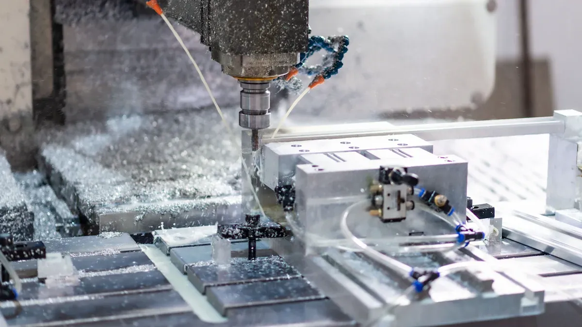
A forging with perfect internal integrity still fails as a finished part if the machining stage misses a tolerance. CNC machining transforms the forged blank into a finished component with exact tooth profiles, bore diameters, and mounting surfaces. The machining stage carries its own defect risks: tool wear, thermal drift, fixture movement, and programming errors. Each risk demands a dedicated control. Precision alone is not enough. The process must also deliver repeatability, meaning part number one thousand matches part number one. Three control layers secure both goals: in-process inspection, rigorous dimensional measurement, and surface finish verification.
In-Process Machining Inspection
In-process inspection catches deviation while the spindle is still turning. The first article inspection sets the baseline for every production run. An inspector measures the first completed part against every drawing characteristic. The setup stays locked until the first article passes. This gate prevents a wrong offset or a misloaded fixture from producing a batch of scrap.
Tool wear drives the most common machining drift. A cutting tool loses edge sharpness over time, and the cut dimension shifts with it. Operators track tool life against a defined limit and measure critical features at set intervals. A boring bar that cuts a bore 0.01 mm oversize at hour two will cut further oversize at hour six. Periodic measurement catches the trend before the bore leaves tolerance.
Thermal growth affects long runs. The spindle, the ballscrew, and the workpiece all expand as the machine warms up. A warm machine cuts differently than a cold machine. Shops manage this effect with warm-up cycles, coolant temperature control, and probe-based compensation. On-machine probing re-establishes the workpiece datum before critical cuts. The probe also verifies feature position after the cut.
Statistical process control turns inspection data into a warning system. Operators plot measurements on control charts against upper and lower limits. A run of points drifting toward one limit signals a process shift. The team corrects the cause before a single part fails. This approach moves quality control from detection to prevention.
For high-precision transmission components, key dimensions receive 100% inspection. Tooth profile, lead, and pitch deviations determine noise, efficiency, and load sharing. A sampled check cannot guarantee every gear in a batch. Full inspection of these characteristics protects the assembly line from a single bad part.
Dimensional Measurement Methods
Different features demand different measurement tools. A shop selects the method based on tolerance, feature geometry, and production volume. The table below summarizes the common methods and their best-fit applications.
| Method | Typical Use | Strength | Consideration |
|---|---|---|---|
| Coordinate measuring machine (CMM) | Complex geometry, first article, audit | High accuracy, full feature data | Slower; best for sampling and setup verification |
| Gear measuring center | Tooth profile, lead, pitch, runout | Direct evaluation against GB, ISO, and AGMA grades | Dedicated to gear features |
| Air gauging | Bore diameter, high-volume runs | Fast, repeatable, operator-friendly | Limited to specific feature types |
| Micrometers and bore gauges | Shaft diameters, simple bores | Flexible, low cost | Operator technique affects results |
| On-machine probing | Datum setting, in-process verification | Catches errors without unclamping | Probe calibration must be maintained |
Gear measurement deserves special attention for transmission parts. A gear measuring center traces the tooth flank and compares the result to the design profile. The output expresses deviation in microns and converts it to a quality grade. Precision ground gears reach GB 6, ISO 6, or AGMA 10 levels. These grades translate directly into low noise and high transmission efficiency. The measurement report documents the grade for every inspected gear.
Measurement uncertainty matters as much as the measurement itself. A gauge with uncertainty close to the tolerance width cannot judge the part reliably. The quality plan matches each gauge to the tolerance it verifies. Calibration records prove that every instrument traces back to a national standard. A calibrated instrument with a documented uncertainty gives the measurement legal and technical weight.
Surface Finish Verification
Surface finish influences fatigue life, wear resistance, and sealing performance. A rough tooth flank concentrates stress and accelerates pitting. A rough bore surface damages mating shafts and seals. Surface finish therefore belongs in the quality plan alongside dimensions.
Profilometers measure roughness parameters such as Ra and Rz. The stylus traces the surface and records the profile. Inspectors compare the reading against the drawing requirement. Critical sealing surfaces and bearing seats receive routine checks. Gear tooth flanks receive checks after grinding, because the grinding process defines the final surface.
Visual and optical methods complement the stylus. A borescope inspects internal features that a stylus cannot reach. Microscopic examination reveals grinding burn, chatter marks, and microcracks. Grinding burn softens the surface and reduces wear resistance. A nital etch inspection exposes tempering effects on hardened surfaces. These checks protect the hardness achieved in heat treatment.
Surface finish is a functional requirement, not a cosmetic one. A gear that meets every dimensional tolerance but fails the finish specification will fail in service.
Process control keeps surface finish stable across a production run. Coolant condition, wheel dressing, and cutting speed all affect the result. A worn grinding wheel raises roughness and can burn the surface. The team dresses the wheel on a defined schedule and verifies finish after each dressing. This discipline holds the finish inside specification for the entire run.
Together, these three control layers give the machining stage its repeatability. In-process inspection catches drift early. Dimensional measurement proves conformance to drawing. Surface finish verification protects function. The next section examines how forging and machining controls connect into one traceable quality system.
Integration of Forging and CNC Machining in Custom Metal Part Manufacturing
Cross-Process Coordination and Traceability
Forging and machining deliver their best results when they operate as one connected system. The forging stage defines the fiber flow and internal integrity. The machining stage defines the final dimensions and surface quality. A change in one process ripples into the other. Process planners therefore set machining allowances that account for forging tolerance and heat treatment distortion. Too little allowance risks a scrapped part after grinding. Too much allowance wastes material and cutting time.
Traceability ties the two stages together. The heat number from the forging record follows the part into machining. The machining record links every measured dimension to that heat number. When an engineer writes a professional article about the integration of forging and CNC machining in custom metal part manufacturing, traceability is the thread that connects every quality claim to a documented fact.
Key Quality Standards and Certifications
Equipment manufacturers expect suppliers to work against recognized standards. Gear accuracy grades follow GB, ISO, or AGMA systems. Surface hardness and case depth follow the approved heat treatment specification. Material certificates trace to national or international standards. A supplier who writes a professional article about the integration of forging and CNC machining in custom metal part manufacturing must back every statement with calibration records and inspection reports.
Common Challenges and Practical Solutions
Distortion after heat treatment ranks as the most persistent challenge. Forged gears often move during carburizing and quenching. Shops solve this problem with controlled quenching, fixture hardening, and a finishing grind after heat treatment. Tool wear and thermal drift follow close behind. On-machine probing and scheduled tool changes keep both effects inside tolerance.
Qingdao Xuxiangtai Machinery Manufacturing Co., Ltd. addresses these challenges through precision forging, tooth profile grinding, and 100% inspection of key dimensions. The company manufactures to customer drawings and welcomes international customers to submit drawings, samples, or technical specifications for custom manufacturing inquiries.
Layered quality control across forging and machining catches defects before assembly. Robust QC delivers measurable value: lower scrap rates, fewer warranty claims, and predictable lead times. Equipment manufacturers should demand documented inspection plans, material certifications, and full traceability from suppliers. Integrated quality control gives sourcing teams a competitive advantage, not a cost center.
FAQ
What does a forging quality control plan include?
A forging plan covers material certification, billet temperature monitoring, die condition checks, fiber flow verification, and final ultrasonic and hardness testing. Each stage carries defined acceptance criteria and documented records.
How do suppliers verify gear accuracy after machining?
Suppliers use a gear measuring center to trace tooth profile, lead, and pitch. The report converts deviations into GB, ISO, or AGMA grades. Precision ground gears reach GB 6, ISO 6, or AGMA 10 levels.
Why does traceability matter for custom metal parts?
Traceability links every finished part to its source heat number and inspection records. A defect investigation becomes fast and precise. Equipment manufacturers gain documented proof of conformance for every delivered batch.
See Also
Avoid Making Incorrect Decisions When Selecting Aluminum Casting Processes
Related products
-
 Contact Us
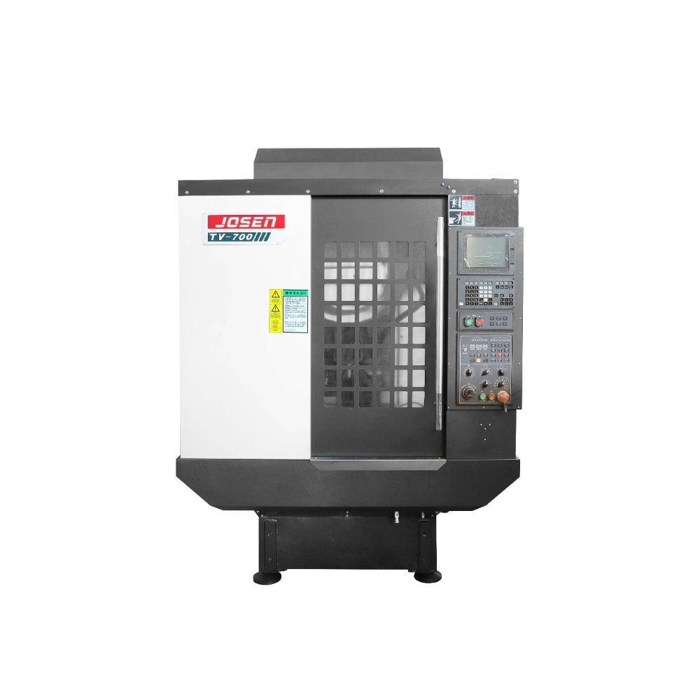
The three axes are designed with direct drive,high inertia motor with large lead screw, three axes acceleration up to 1G, from standstill to 48m/min, just 0.2 seconds.Standard 21 servo tool changer.
-
 Contact Us
NEW GLASS SODA MAKER BEST CARBONATOR(GLASS BOTTLE) NEW ARRIVALS SODA STREAM MAKER HOUSEHOLD SPARKLING WATER MAKER WITH GLASS BOTTLE
-
 Contact Us
The oil-immersed transformer is a new type of high-performance transformer with a more reasonable structure and better performance.
-
 Contact Us
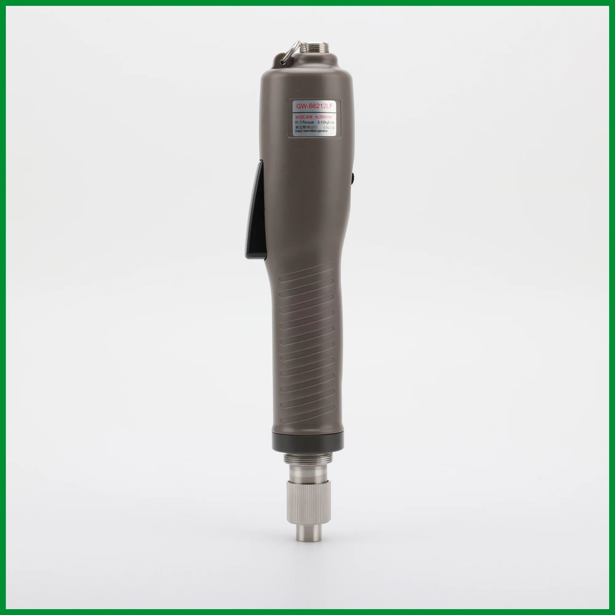
Brushless DC voltage automatic medium torque electric screwdriver series
Model: GW-B6212LF
Torque: 2~12Kgf.cm
Free Speed: HI 2000 / LO 1500 r.p.m -
 Contact Us
High speed optimization Timber cutting optimizing Cross-cut saw and precision cutting
Automation production line.
Reviews
There are no reviews yet.